Product Description
Nonstandard Industry MADE-TO-ORDER Or PLW Plywood Case Chain Sprocket Motorcycle Parts
Product Description
1. Produce strictly in accordance with ANSI or DIN standard dimension
2. Material: 1045 steel / Stainless Steel 304 & 316
3. Standard: ANSI, DIN, JINS, ISO, Standard America or customer drawing
4. Pilot bore, finished bore, taper bore and special bore
5. Bright surface and high precision
6. Advanced heat treatment and surface treatment craft
7. Best quality and competitive price
8. Welcome OEM / ODM
9. Processing equipment: Hobbing machine, Slotting machine, CNC lathes and other equipment.
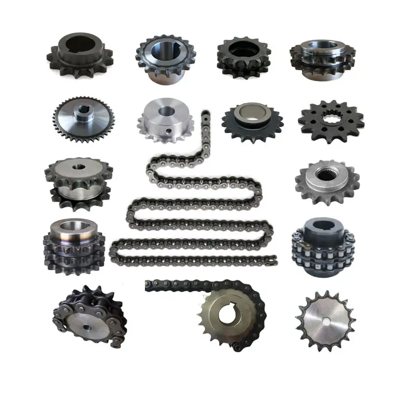
10. Sprocket models: Contains special sprocket according to customer’s drawings, standard sprocket (American standard and metric).
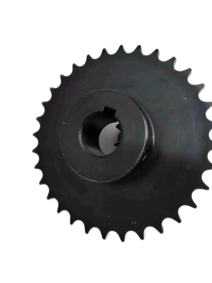
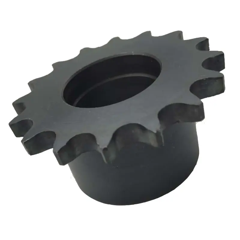
| Product name | Zinc-Plated Driving Sprocket From China (05B16T-1) |
| Materials Available | 1. Stainless Steel: SS304, SS316, etc |
| 2. Alloy Steel: C45, 45Mn, 42CrMo, 20CrMo, etc | |
| 3. OEM according to your request | |
| Surface Treatment | Heat treatment, Quenching treatment, High frequency normalizing treatment, Polishing, Electrophoresis paint processing, Anodic oxidation treatment, etc |
| Characteristic | Fire resistant, Oil resistant, Heat resistant, CZPT resistance, Oxidative resistance, Corrosion resistance, etc |
| Design criterion | ISO DIN ANSI & Customer’s Drawing |
| Size | Customer’s Drawing & ISO standard |
| Application | Industrial transmission equipment |
| Package | Wooden Case / Container and pallet, or made-to-order |
| Certificate | ISO9001: 2008 |
| Advantage | Quality first, Service first, Competitive price, Fast delivery |
| Delivery Time | 20 days for samples. 45 days for official order. |
View more products,please click here…
Detailed Photos
Company Profile
| Standard Or Nonstandard: | Nonstandard |
|---|---|
| Application: | Motorcycle, Machinery, Marine, Agricultural Machinery, Car, Industry |
| Hardness: | Hardened Tooth Surface |
| Material: | Alloy Steel/Stainless Steel |
| Type: | Sprocket |
| Sample: | for Free |
| Samples: |
US$ 0/Piece
1 Piece(Min.Order) | |
|---|
| Customization: |
Available
| Customized Request |
|---|
Calculating Torque Requirements for a wheel sprocket Assembly
Calculating the torque requirements for a wheel sprocket assembly involves considering various factors that contribute to the torque load. The torque requirement is crucial for selecting the appropriate motor or power source to drive the system effectively. Here’s a step-by-step guide:
- 1. Determine the Load Torque: Identify the torque required to overcome the resistance or load in the system. This includes the torque needed to move the load, overcome friction, and accelerate the load if applicable.
- 2. Identify the Sprocket Radius: Measure the radius of the sprocket (distance from the center of the sprocket to the point of contact with the chain or belt).
- 3. Calculate the Tension in the Chain or Belt: If using a chain or belt drive, calculate the tension in the chain or belt. Tension affects the torque required for power transmission.
- 4. Account for Efficiency Losses: Consider the efficiency of the system. Not all the input power will be converted into output power due to friction and other losses. Account for this efficiency in your calculations.
- 5. Use the Torque Equation: The torque (T) can be calculated using the following equation:
T = (Load Torque × Sprocket Radius) ÷ (Efficiency × Tension)
It’s essential to use consistent units of measurement (e.g., Newton meters or foot-pounds) for all values in the equation.
Remember that real-world conditions may vary, and it’s advisable to add a safety factor to your calculated torque requirements to ensure the system can handle unexpected peak loads or variations in operating conditions.
Using wheel sprocket Assembly in Robotics and Automation
Yes, wheel sprocket assemblies are commonly used in robotics and automation systems to transmit power and facilitate movement. These systems offer several advantages for robotic applications:
- Efficiency: wheel sprocket assemblies provide efficient power transmission, ensuring smooth and precise movement of robotic components.
- Compact Design: The compact nature of sprockets and wheels allows for space-saving designs, making them ideal for robotic applications where space is limited.
- Precision: Sprockets and wheels with accurate teeth profiles provide precise motion control, crucial for robotics and automation tasks that require high levels of accuracy.
- Low Noise: Properly lubricated and maintained wheel sprocket systems generate minimal noise during operation, contributing to quieter robotic movements.
- Customizability: wheel sprocket assemblies can be customized to suit specific robotic requirements, such as different gear ratios, sizes, and materials.
- Multiple Configurations: Depending on the robotic application, different configurations like single or multiple sprockets, idler sprockets, or rack and pinion systems can be used.
- High Load Capacity: Sprockets made from durable materials like steel can handle substantial loads, making them suitable for heavy-duty robotic tasks.
Examples of robotics and automation systems that commonly use wheel sprocket assemblies include:
- Robotic Arms: wheel sprocket systems are utilized in robotic arms to control their movement and reach.
- Automated Guided Vehicles (AGVs): AGVs use wheel sprocket assemblies for propulsion and steering, enabling them to navigate autonomously.
- Conveyor Systems: In automated factories, conveyor belts are often driven by sprockets and wheels for efficient material handling.
- Mobile Robots: Wheeled mobile robots use wheel sprocket assemblies to drive their wheels, enabling them to move in various directions.
- Robot Grippers: wheel sprocket mechanisms can be integrated into robot grippers to facilitate gripping and handling objects.
The choice to use wheel sprocket assemblies in robotics and automation depends on the specific application requirements, load capacity, precision, and environmental conditions. By selecting the appropriate sprockets, wheels, and materials, engineers can ensure reliable and efficient robotic performance in a wide range of automated tasks.
Calculating Gear Ratio for a wheel sprocket Setup
In a wheel sprocket system, the gear ratio represents the relationship between the number of teeth on the sprocket and the number of teeth on the wheel. The gear ratio determines the speed and torque relationship between the two components. To calculate the gear ratio, use the following formula:
Gear Ratio = Number of Teeth on Sprocket ÷ Number of Teeth on Wheel
For example, if the sprocket has 20 teeth and the wheel has 60 teeth, the gear ratio would be:
Gear Ratio = 20 ÷ 60 = 1/3
The gear ratio can also be expressed as a decimal or percentage. In the above example, the gear ratio can be expressed as 0.3333 or 33.33%.
It’s important to note that the gear ratio affects the rotational speed and torque of the wheel sprocket. A gear ratio greater than 1 indicates that the sprocket’s speed is higher than the wheel’s speed, resulting in increased rotational speed and reduced torque at the wheel. Conversely, a gear ratio less than 1 indicates that the sprocket’s speed is lower than the wheel’s speed, resulting in decreased rotational speed and increased torque at the wheel.
The gear ratio is crucial in various applications where precise control of speed and torque is required, such as bicycles, automobiles, and industrial machinery.


editor by CX 2023-12-04